What it takes to render crowds
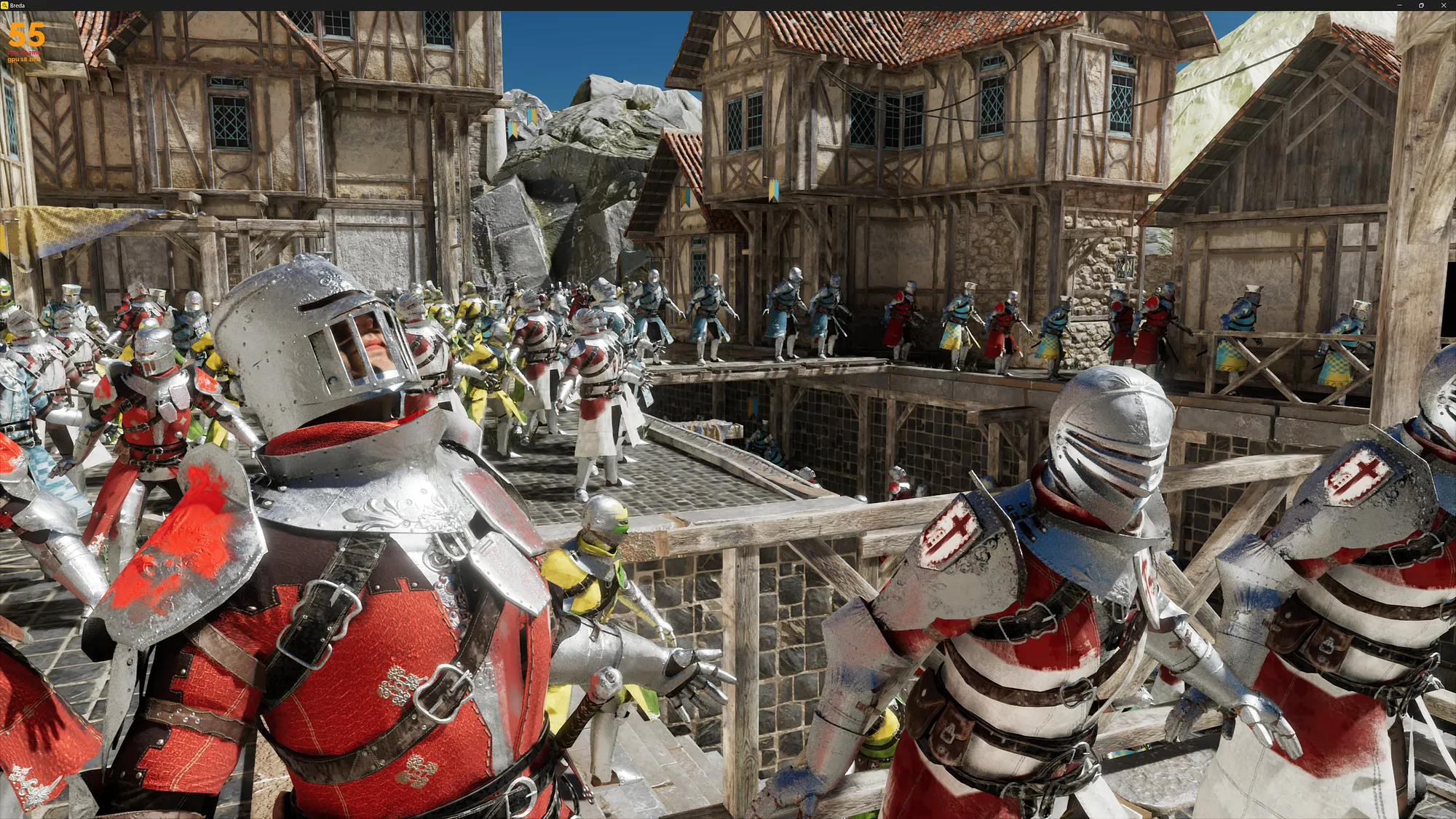
Crowd simulations have been common in games for a while now, but they usually only had to work for rasterization. Now that ray tracing is becoming more popular, new challenges have appeared. This blog post covers how we implemented animations and crowds in our testing framework “Breda” here at Traverse Research.
There are various challenges that need to be tackled while implementing such a system. First of all, the large number of vertex animations means we need an optimal GPU implementation to update all the meshes into their animated poses. Since these crowds will be used in both our path tracer and hybrid renderer, we also must take acceleration structure building into account for the animated meshes. These require a persistent set of vertices in their animated pose, which means that we will need a duplicate vertex buffer for each animated instance!
Other than that we should keep in mind that we’ll need motion vectors for the animated geometry, and ideally have the ability to reuse as much of the animation state as possible to make the crowds perform well.
Our animation system
Our animation system consists of a few basic types and concepts. We import most of our animation data from glTF, and store it in our own asset format. This format still closely resembles glTF.
Animations
An animation in our engine is defined as a set of channels, where each channel has an output type (translation, rotation or scale). A channel defines the values for that output type for each key time-point in the animation. Every channel has an output index.
We apply animations to animation samples to sample one specific time point for that animation.
Animation Samples
Animation samples contain the state of an animation for one time-point. The channels in an animation directly write these values into the animation sample. A sample can contain an arbitrary number of outputs, where each output is the combination of a rotation, translation and scale. These can be combined into a transformation matrix later.

Note that not all outputs in the sample have every type of channel. In this example, if we were to apply output 1 to a transform, we would only override the rotation and translation. We keep the scale from the original transform.
Skeletons
A skeleton is defined by a set of bones that are parented together to form a hierarchy. Each bone has a default position, called the bind pose (or T-pose). Skeletons and their bones are in local space, because we will want to reuse the same skeleton for multiple meshes at different locations. This requires a conversion step from glTF, as that format defines them in world-space.
Skeleton Samples
These are similar to animation samples, in the sense that they contain the state of the bones in a skeleton for a specific time-point. In fact, each skeleton sample contains an animation sample! When we animate a skeleton, we first apply the chosen animation to this animation sample. Each transform output of the animation sample corresponds to a bone, and we apply the rotation, translation and scale overrides to that bone. We now have a set of bones in their animated state.
Next up we apply the hierarchy of the bones. This involves multiplying the bone transforms in the right order. E.g.: the hand bone is attached to the arm, which is attached to the shoulder.

Vertex Buffers
Now that we have the final position of each bone in our skeleton sample, we can apply the bones to the vertices in a vertex buffer. Because we need to build a bottom level acceleration structure, these vertices must be persistent. We can’t rely on the old rasterization trick of transforming the vertices during the draw calls.
Actually, there is still one thing we have to do before we can apply the bones to the vertices. We must first undo the bind-pose by applying the inverse-bind-matrix (ibm) to each vertex. To understand why, you have to realize that the vertices in their bind pose are already transformed by the bones. If we were to directly apply the new bone position, we would essentially have applied that bone twice. The ibm of a bone will transform that bone back to the origin of the world. If we apply it to a vertex, then we are moving that vertex back towards the origin (0,0,0), which means the vertex position is now relative to the bone. At this point, we can apply the new position of our animated bones to the vertices, and they will correctly end up relative to the bones.

In the example above you can see this happening. If we move the foot of the skeleton, then we want to move the vertices in the leg along the long green vector (the transform of the bone). However, the small red vector was already applied (the bind pose of the bone). First we undo the bind pose, then we can apply the new bone position.
In our implementation, we pre-apply the ibm to each bone after we chain the bones together.
Now, applying the bones to the vertices is fairly straightforward. First we read the vertices from the bind-pose vertex buffer in a compute shader, and then we multiply them with the corresponding bones. Each vertex can define up to four bone indices, and a weight for each of those bones.
Finally we write the animated vertex away to the animated vertex buffer.


World Infrastructure & Crowds
The previous section discussed what the animated data and update logic looks like, but it did not yet touch on how we actually set up these animations in the world. Most importantly, it did not involve anything about crowds yet.
Hierarchy
Central in our framework is a hierarchy of nodes that all have a transform. These represent the objects in our world. Each node can have an animated vertex buffer attached to it, but a node’s transform can also be animated directly.
Vertex buffers are not directly attached to nodes, but rather we attach a small container (we call them “meshes”) composed of references to a vertex buffer, skeleton sample, bottom level acceleration structure and materials. These “meshes” can be composed separately, and reused between multiple nodes.
Attaching a mesh to a node means we update our draw calls and add an acceleration structure instance to our TLAS.
Node Animation
As mentioned before, we can also directly animate nodes in the world. Think for example of rotating objects. We don’t have to apply vertex animation here, we just need to override a node’s transform in the hierarchy directly. This is why we can bind nodes in our hierarchy to a specific animation sample. We gather these, and apply the transforms in a compute pass.
Skeleton Parenting
We’d very much like it if our crowd actors could hold items in their hands, or wear hats. To do this, we should be able to parent nodes to bones in a skeleton. But this is a problem, because our skeletons are not actually a part of the hierarchy. Instead they are in local space so that we can reuse them. Fortunately this is simple to solve. We can provide nodes with a skeleton sample and bone index, and patch the node’s transform in a compute pass that reads and applies the right bone.

Crowd Instancing
A hierarchical approach like this allows us to reuse a lot of animation, and forms the backbone of our crowd system. For example, we can decide to load a single skeleton, and animate it ten times at different time points. We can then apply those ten skeleton samples to 100 unique vertex buffers. Those 100 vertex buffers can be combined with different sets of materials to create many unique “meshes”. Each mesh can then be added to one or more nodes to create large crowds with limited animation updates.
Because we need to make a full copy of the vertex buffer for each unique animated instance, reusing these also saves a lot of memory.

Double Buffering for motion vectors
Since we apply all sorts of graphics effects, we often need motion vectors so that we can retrieve temporal information from the previous frame. This goes for vertex animated geometry as well. Fortunately, we already need to keep a copy of the animated vertex data around for ray tracing. Double buffering the positions for those buffers is a small extra cost that allows us to then always retrieve the previous frames’ vertex positions for a specific mesh. Subtract those from the current positions, and you have your motion vectors.
BLAS building and refitting
Every time we update a vertex buffer in the animation system, the bottom level acceleration structure that uses the buffer must also be updated. This can be done by either rebuilding it completely, or by performing a refit. If the changes in geometry are small enough, a refit is often cheaper and still gives good tracing performance. In our framework we rebuild once every N frames, and do refits for the rest. We do this because the BLAS quality deteriorates over time while refitting. A heuristic can be used here to determine when a rebuild should happen.
The rebuilds and refits can be batched in most modern graphics APIs. This gives the driver the opportunity to limit the number of dispatches for better performance.
Other world stuff
This sums up the main tasks in our world update regarding animation. Of course, there’s more engineering around it. Sorting the draw calls and setting up our TLAS requires extra work. We have some logic in place that ensures that animation updates always run at least once so that we never have any uninitialized state.
Animating a crowd with many instances of the same mesh, but with different materials, also comes with some downsides. Draw call sorting depends on the material, so you’ll have to split up your instanced draw calls, and change pipeline state. BLASes require you to specify geometry flags that tell you whether a triangle is opaque or not, which means you’ll have to build new BLASes when the opacity of the materials between instances changes. Solving these is not in the scope of this blog post, but be warned that you will run into these!
Compute on the GPU
Now that we have all the theory down, we are still left with a considerable amount of work that the GPU has to do. How do we implement this optimally?
Compute work
Our animation system does a total of 7 compute dispatches, regardless of how many animated objects we have.
- Read animation channels and write to animation samples.
- Apply animation samples to bones.
- Apply the skeleton hierarchy to the bones.
- Apply the ibm to each bone, and calculate the normal matrix.
- Apply bones to vertex buffers.
- Apply animation samples to nodes.
- Apply bones to nodes on the hierarchy.
Optimizing & bindless rendering
The main optimization that we can do is to batch as much work as possible. Launching a compute pass per skeleton to update its bones would be bad for performance because it comes with some overhead. Furthermore, for small skeletons it would mean that a large portion of the threads would be idle.
The same thing goes for all the other passes: we have many small buffers containing similar data. If all this data had been in a single large buffer, then a single update step would have been easy. Fortunately for us, we have a bindless rendering setup that allows us to dynamically access any buffer from the GPU. This means that we can launch a single compute dispatch that goes over all the buffers, and in turn all the data in those buffers.
If you would like to know more about our bindless implementation, check out our blog post series by Darius Bouma on setting up a bindless renderer. https://blog.traverseresearch.nl/bindless-rendering-setup-afeb678d77fc
Now, the technique I used to batch all these operations is by building a prefix sum. I’ve described a fast implementation of this algorithm in my previous blog post, which you can find here: https://blog.traverseresearch.nl/fast-cdf-generation-on-the-gpu-for-light-picking-5c50b97c552b
Quickly summarized, we want to know the total number of operations we have to perform. For example, if we have 50 skeletons in separate buffers with 10 bones each, then we have a total of 500 bones that need to be updated. We would need to launch a compute pass with 500 threads, each of which will update a single bone.

By calculating a prefix sum, we can use each thread’s global index to deduce the skeleton and bone index to update. This is done using a binary search in the prefix sum array. This array stores for each buffer how many elements came before it. For example, the first buffer has seen 0 elements. The second buffer has seen all elements in the first buffer, and so forth.
We can repeat this prefix sum implementation for each pass in our animation system. It can be done for the animation channels, the bone buffers and any other data that is spread out over many small buffers.


Shortcomings / Future work
Overall we are very happy with the implementation we came up with, though there are a few shortcomings still which I’ll list here.
Firstly, we don’t have access to the world space transforms of all our actors, because animations happen on the GPU. This was not a big problem for our demo, but in a more game-like scenario you’d quickly run into issues here. Proposed solutions are to mimic parts of the animation pipeline on the CPU depending on which transform you need to know, or to do a read-back (which would mean your transforms are always a frame behind).
We also didn’t tackle animation blending or bone labeling. These were simply not a priority for us, but are on the backlog. Perhaps we’ll release a blog post in the future to cover these.
Lastly, our crowds can still benefit from some changes. For example, adding LODs to not just the crowd actors, but also their skeletons and animations could improve performance. This was however not in scope for us at the time, as it would likely require a lot of manual tweaking by an artist. The same thing goes for adding more variation to the clothing worn and objects held by actors in the crowd. An interesting talk on these topics can be found here: https://www.youtube.com/watch?v=Rz2cNWVLncI.
I hope this was helpful! Feel free to leave a comment if you have any questions, and I’ll do my best to answer them.
Dec 24, 2023